Manufacturing is becoming faster, smarter, and more automated.
Factories are introducing robots, automated production lines, and AI vision systems to reduce reliance on manual inspection, improve efficiency, and maintain more consistent product quality.
From checking whether components are installed correctly to detecting scratches, measuring dimensions, reading labels, and guiding robotic arms, cameras are becoming the “eyes” of modern industrial equipment.
However, installing a high-resolution camera does not automatically create a reliable inspection system.
Many projects encounter problems after sampling:
These problems are rarely caused by resolution alone. They usually result from a mismatch between the image sensor, lens, lighting, working distance, shutter type, interface, image settings, and inspection algorithm.
Therefore, the first question should not be:
“How many megapixels does this camera have?”
It should be:
“What does the machine need to see, and under what conditions?”
Traditional manual inspection depends heavily on the experience, concentration, and working condition of the operator.
As production speed increases, inspectors may miss small defects. Different workers may also make different judgments about the same product, making it difficult to maintain consistent quality standards.
Machine vision systems can inspect products continuously, apply the same standards to every item, record the results, and connect with automated sorting or equipment-control systems.
Today, machine vision cameras are widely used in:
However, every application requires the camera to see something different. A camera suitable for checking whether a large component is present may not be able to detect a tiny scratch on a reflective metal surface.
This is why there is no single camera module that can solve every machine vision application.
Before selecting the sensor, lens, or interface, define exactly what the system needs to inspect.
For example:
The most important information is usually the physical inspection area and the smallest feature that must be detected.
For example, inspecting whether a large connector is installed may only require moderate resolution. Detecting a 0.2 mm defect may require higher resolution, a narrower field of view, controlled lighting, and suitable image tuning.
The camera should therefore be selected according to the actual inspection target—not simply according to the highest available specifications.
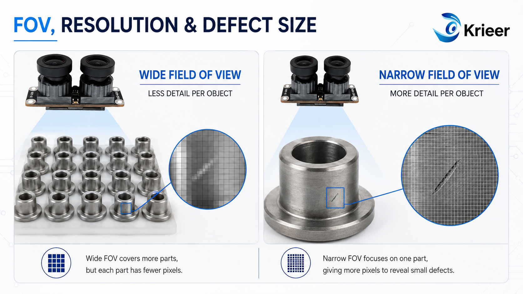
Resolution is important, but it must be evaluated together with the field of view and minimum defect size.
Suppose the camera needs to cover an area 200 mm wide, and the image has 2,000 horizontal pixels. In theory, each pixel represents approximately 0.1 mm of the object.
However, if a 0.2 mm defect only occupies two pixels, it may still be difficult to identify reliably. The inspection algorithm normally needs additional pixel coverage to handle image noise, object-position variation, lens distortion, and changes in lighting.
Before deciding whether the project requires 5MP, 8MP, or 12MP, confirm:
Higher resolution also increases image data, transmission bandwidth, storage requirements, and processing load. Unnecessarily high resolution may increase system cost and latency without improving the final inspection result.
Production-line applications often require the camera to capture moving products. However, a high frame rate alone does not guarantee a clear image.
Frame rate determines how many images the camera can output each second. Exposure time determines how long the sensor collects light for each image.
If the exposure time is too long, a fast-moving product may still appear blurred—even when the camera supports a high frame rate.
Capturing moving objects clearly may require:
A stronger light source or synchronized strobe lighting can help shorten the exposure time and freeze moving objects more effectively.
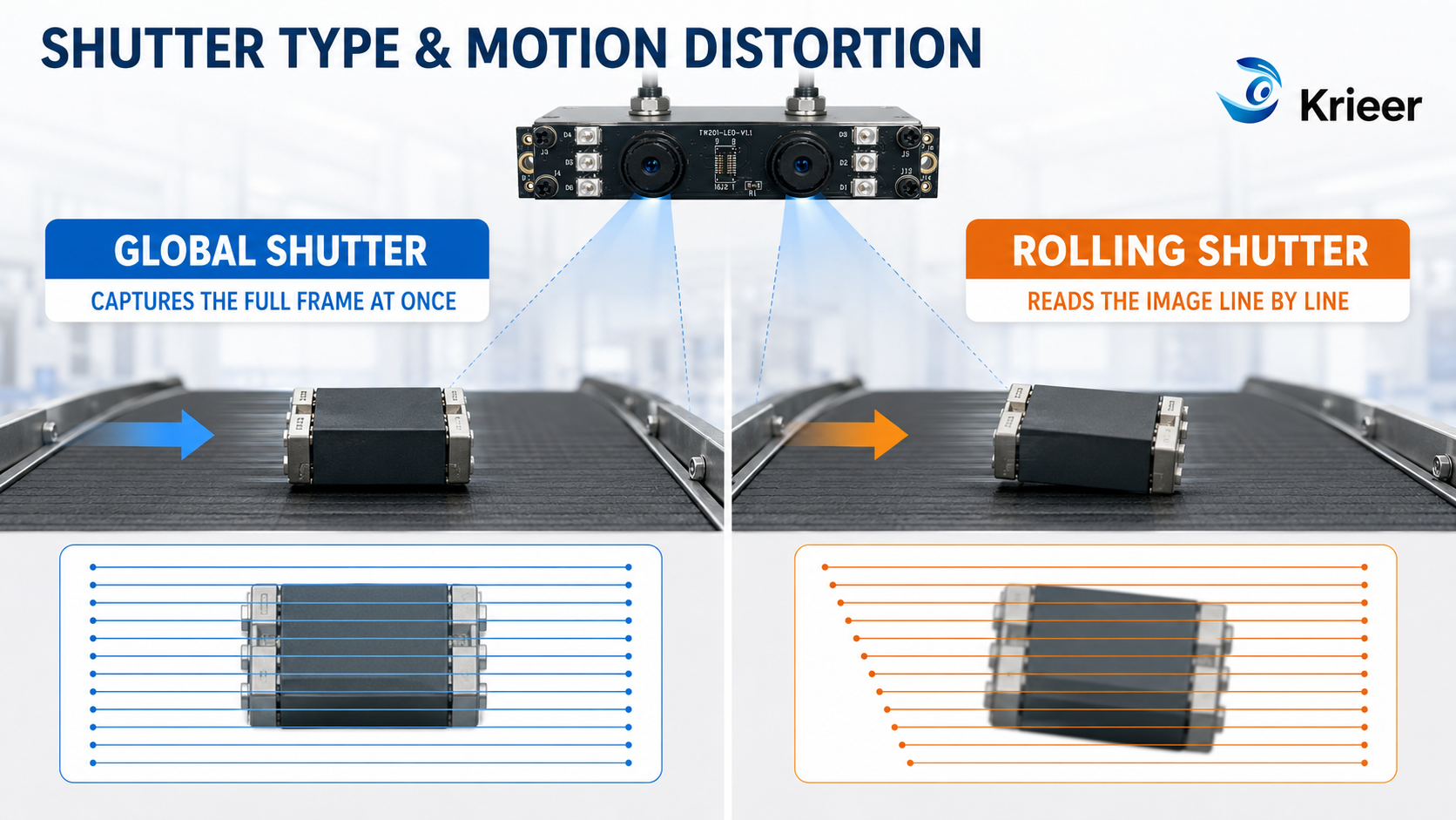
Shutter type can directly affect the shape and position of moving objects.
A rolling-shutter sensor captures the image line by line. When an object moves quickly, the result may appear tilted, stretched, or distorted.
A global-shutter sensor captures the entire frame at nearly the same time, making it suitable for many motion-related applications, including:
However, rolling shutter is not always the wrong choice. If the product stops during image capture or moves slowly under controlled conditions, a rolling-shutter camera module may provide sufficient performance at a more suitable cost.
The correct choice depends on the object speed, exposure time, lighting conditions, and required inspection accuracy.
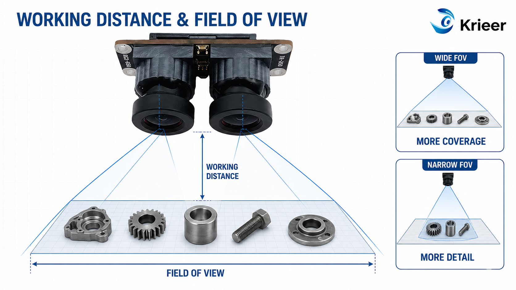
Working distance is the distance between the camera lens and the object. Field of view is the physical area that the camera can see.
These two values determine how large the object appears in the image and how much detail the system can capture.
A wider field of view covers a larger area, but the object receives fewer pixels. A narrower field of view shows more detail but covers a smaller inspection area.
Before selecting the lens, confirm:
If these conditions are not confirmed before sampling, the camera may produce a clear-looking image but still fail to capture the details required by the inspection algorithm.
Many problems that appear to come from the camera are actually caused by lighting.
Industrial products may have reflective, transparent, curved, textured, or dark surfaces. Changes in ambient light can also make the same product appear different throughout the day.
Different inspection tasks require different lighting methods:
The camera module may also need adjustable exposure, gain, white balance, anti-flicker settings, and synchronization controls.
Whenever possible, testing should use the actual product, production speed, working distance, and lighting environment.
Autofocus is common in consumer cameras, but it is not automatically better for industrial inspection.
For equipment with a fixed working distance, a properly adjusted fixed-focus lens usually provides:
Autofocus may be helpful when different products appear at different distances. However, reflective or low-contrast surfaces may cause the camera to search repeatedly or focus on the wrong area.
For fixed inspection stations, stable focus and sufficient depth of field are often more important than autofocus.
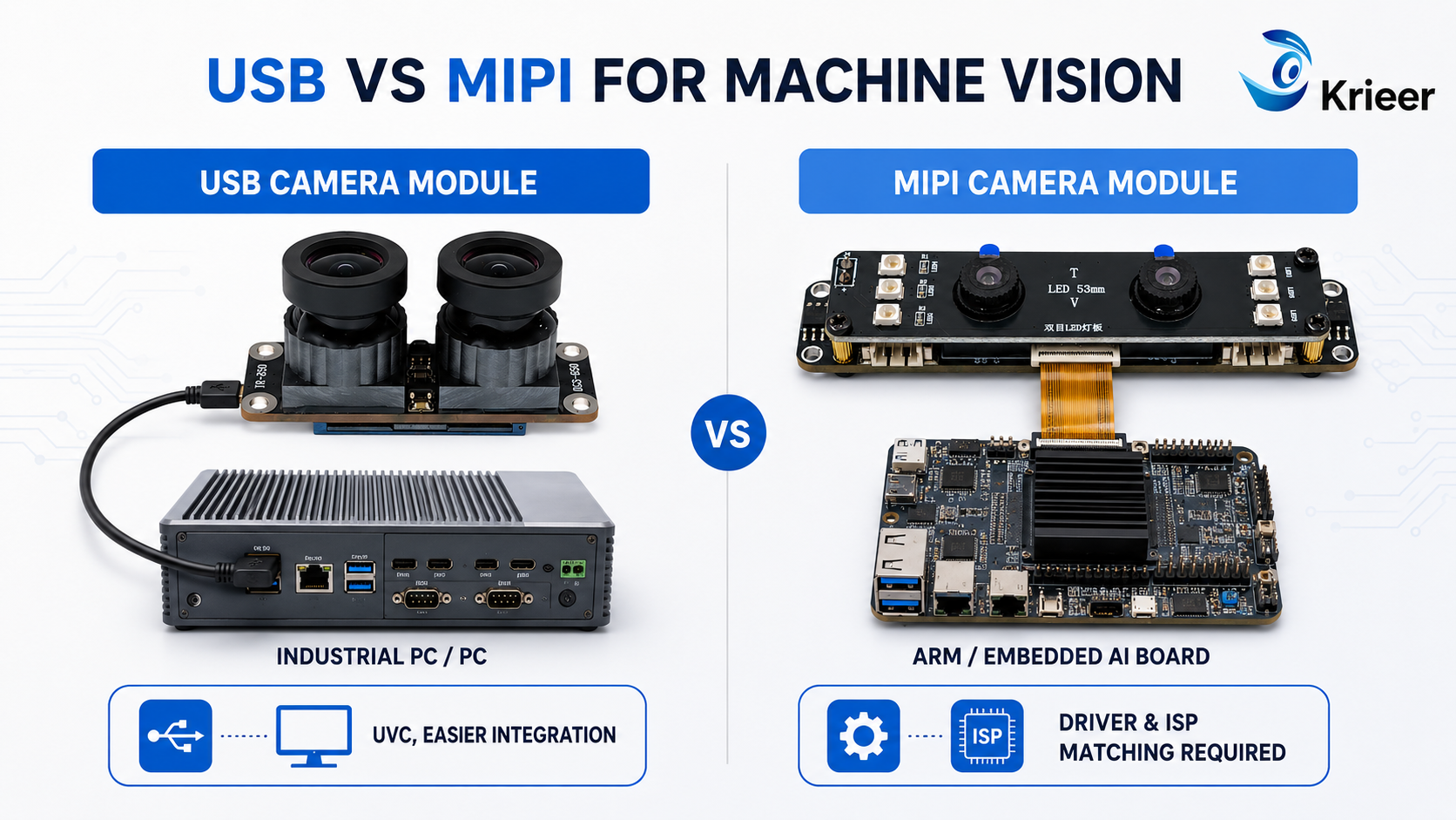
A camera module that works on a PC may not necessarily work inside the final industrial device.
The interface must match the host platform, operating system, bandwidth, installation space, and development capability.
USB camera modules are commonly used with PCs, industrial computers, and compatible Android or Linux systems. UVC compatibility can reduce development difficulty and shorten the sample-testing process.
MIPI camera modules are suitable for ARM platforms, embedded AI boards, and compact devices. However, they require confirmation of sensor drivers, ISP compatibility, MIPI lanes, clock settings, and FPC pin definitions.
The project should also consider cable length, connector stability, electromagnetic interference, image format, internal layout, and future maintenance.
The best interface is not necessarily the one with the highest bandwidth. It is the one that integrates reliably with the complete device.
Consumer cameras often use automatic exposure, white balance, sharpening, denoising, and automatic gain to make images look brighter and more attractive.
Machine vision systems have a different goal: every image must remain stable enough for repeated algorithm analysis.
If automatic exposure changes the brightness between frames, the inspection algorithm may produce different results for the same product.
Depending on the application, the camera may need:
The goal is not simply to produce an attractive image. It is to provide stable and repeatable image data for inspection and measurement.
To select a suitable machine vision camera module, prepare the following information:
Product photos, inspection videos, equipment drawings, and examples of acceptable and defective products can make camera selection more accurate.
As manufacturing becomes more automated, the camera module is no longer only an image-capturing component. It is part of the complete inspection and decision-making system.
Krieer provides customized camera module solutions for industrial inspection, robotics, automated equipment, barcode recognition, smart terminals, and embedded vision applications.
Our team can assist with:
A reliable machine vision system does not begin with the camera that has the highest specifications.
It begins with understanding what the machine needs to see, how fast the object moves, how the inspection area is illuminated, and how the camera will integrate with the final device.
By providing the inspection target, minimum defect size, working distance, field of view, object speed, host platform, and expected quantity, customers can receive a camera module solution that better matches their actual application.


